Proper filtration is absolutely necessary if you want peak performance from your hydraulic system. If you think just selecting a filter will be easy, think again. There are a series of considerations, simple guidelines, to take into account before filters are installed. Know and understand hydraulics and the application, as well as, the requirements of its performance.
Filter sizing can be a problem if you aren’t sure of the system operation and what its primary function is. The point is, you shouldn’t just remove a filter and install a new one in its place without making sure you have the correct filter to help get the job done efficiently and effectively. Let’s take a look at some considerations when trying to insure proper filtration.
First of all, one thing is for sure, there are many different systems, performing may different applications, with many different requirements. This paper will use terms like, “usually,” “typically,” and “generally.” System requirements vary periodically but “generally” speaking, sizing a filter to a system is critical and could be the difference between a smooth running operation and a poor one. Proper filtration is absolutely necessary to have a healthy longevity of a hydraulic system.
Let’s start with a series of questions that should be considered when making an accurate determination of installing the correct filter.
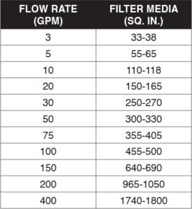
1. What is the flow rate of the pump? The first consideration is knowing the rate of flow of the process fluid. This would tell us how large or small the surface area of the filter media should be (sq. in.). Please note the chart below for an approximation of the size of the filter media and the corresponding flow rates. Keep in mind that all figures are approximate and based on 149 microns at standard operating temperature of 100°F. This allows for flexibility when using other levels of filtration and can be used as a guideline.
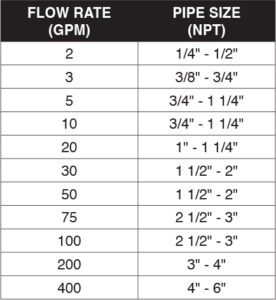
2. What is the pipe size? Flow rate and pipe size go hand in hand. If you have a flow rate of 50 gpm, the filter must be the correct size in order to keep the pressure drop in check of the fluid passing through it. A pump creating flow of 50 gpm, for example, will cause a totally lower pressure drop flowing through a 3” npt line, than it will a 1” npt line. Knowing the pipe size will narrow the options you have to adequately start determining the correct filter size. A general reference chart follows for flow rate/pipe size sizing.
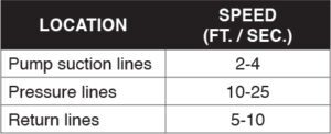
Typically,” velocity in fluid conductors should be flowing adequately to have the system running smoothly and efficiently. A chart below shows what the velocity of the process fluid should be in various lines.
3. What is the working system pressure? In order to not only select the proper size but consider selection based on the question, “Can this filter handle the pressure it is going to see?” If a filter collapses in use, not only is it going to lose its integrity and break down because it couldn’t withstand the high pressure, but it will cause the system to become damaged or break down. When a filter collapses, fragments of epoxy or filter media will get into the flow stream and cause damage to downstream equipment.
4. What is the fluid? Is it standard hydraulic fluid? Is it a petroleum based product where fluid and equipment will work in harmony? It is extremely important to have your system components, not only filters, to be compatible with the fluid. Otherwise, you are asking for serious system damage or destruction. Damage could be caused to equipment and seals creating leaks and allowing serious contamination problems to occur.
5. What is the viscosity of the fluid? Viscosity of standard hydraulic fluid is 150-200 SUS, simply stated. However, what if there was a process fluid in the system of 250-300 SUS? I would expect the system designers recommended the fluid for the application. A fluid with higher viscosity is thicker than standard hydraulic fluid. This must be taken into consideration because the fluid that has a higher viscosity will create a higher pressure drop flowing through the system especially during cold weather start-ups. When passing through filters it is necessary to have them strong enough to be able to handle higher pressure drops or filter collapse and destruction may occur. Allowable initial pressure drops very widely from component to component so make sure you’re aware of what your system requires.
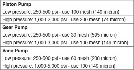
6. What type of pump is being used? Is it a piston, gear, vane, or other type of pump? This would be important when installing a new or replacement suction strainer. Different pumps sometimes require more critical protection. The pump is the heart of the system. If it fails, the system fails. More directly said, if the pump dies, the system dies. Just like the human heart. If the heart quits or dies, the body does, too. Suction strainers have one purpose and one purpose only in a hydraulic system. That is to protect the pump. The chart that follows is a “general” guide to adequate protection for the pump in operation.
7. What type of filter is required? In-tank or in-line, when referring to suction straining? Replacement filter for an existing housing only? Replacement filter with a replacement cartridge in the housing? It is important to visually get this in your mind if you are unsure of what the requirement may be. Is the filter media, wire cloth, cellulose, synthetic? If so what is the synthetic material and has it been performing properly?
8. Will the system be operating continuously, intermittently, or infrequently? If a system is in operation continuously, possibly working 3 shifts per day, the filter selection may be one that can withstand the rigors of the constant operation. Is it a filter made with wire cloth media instead of cellulose or micro-glass media? If the filter will be used in a system that only operates once in a while, a less costly one may possibly be installed. The important decision to be made here is to install a filter that is best for the operation. The worst possible occurrence is machine break down because the filter installed couldn’t withstand the operation.
9. What is the system operating temperature? Hydraulic system standard operating temperature is “usually” around 100°F. If the temperature runs hotter than standard, it most certainly must be kept in check. Too hot a system can destroy seals and cause leakage, as well as, break down the fluid. Either a cooler should be installed or the proper seals, for example, Buna, Teflon, Viton, etc, must be used to be compatible with the operation.Hydraulic system standard operating temperature is “usually” around 100°F. If the temperature runs hotter than standard, it most certainly must be kept in check. Too hot a system can destroy seals and cause leakage, as well as, break down the fluid. Either a cooler should be installed or the proper seals, for example, Buna, Teflon, Viton, etc, must be used to be compatible with the operation.
10. Is the system indoors or outdoors? Always realize that moisture is the second most damaging contaminant in any system. Outside the surrounding environment will most likely cause moisture to get into the system. Hygroscopic breathers may be necessary to prevent moisture from getting into the system. However, even some indoor systems, depending on the geographical region, moisture can play havoc with a system, too. It may be necessary to use stainless steel filters with housings to prevent corrosion from occurring. If you are not sure if the metal “details” of a filter require stainless steel or plated steel, ask yourself the question, “what are the other components in the system made of?” Therein may answer your question of which type to use.
11. What about the air that gets into the reservoir? The tank breather is one area which seems to be neglected and not serviced as often as it should. As fluid levels rise and fall in the reservoir, atmospheric air enters the reservoir and is expelled from the reservoir. Air carries both particle and moisture contaminants. A hygroscopic breather may be warranted. Sizing of this component is just as critical as any other system filter. Air intake is measured in cubic feet per minute (CFM or SCFM). Sizing is important and remember it is permissible to oversize your air filter, too. A “general” rule of thumb to follow when sizing a tank breather is to use the following formula; Gallons per Minute, divided by 7.5 = CFM. In short, GPM/7.5 = CFM. For example, if the system is running 100 gpm, that would be divided by 7.5, which equals 13.3 CFM. Most small breathers available are rated for up to 35 CFM, and are available to as fine as 3-5 micron filtration.
12. What mesh or micron should be used? To completely size a filter, the level of filtration is critical. This could make or break an efficiently running operation. Suction lines should be no finer than 200 mesh (74 micron). Having too fine of filtration on the suction side may cause pump cavitation. Follow a few general rules above in the chart in Item #6. Protecting the pump in an effective manner is critical. “Typically,” the pressure line has the finest filtration in the system. It could be as fine as being in the sub-micron area depending on the application. The return line should be anywhere from 74 micron to 5 microns, depending on the application. This is an area that should be looked at closely because there are so many different applications with so many different requirements and with so many various scenarios. Know your equipment.
These are points to consider when sizing a filter to a system in order to keep it running in a smooth and efficient manner. To protect the entire system, you want adequate filtration in all lines; suction, pressure, return, and tank breather. Contamination is the cause of anywhere from 80%-90% of a system failing. The simple point here is if you want to reduce the downtown your system will see, reduce the contamination in it. Period.
Sizing filters correctly is the first step to reducing downtime along with having a properly scheduled maintenance program. Hydraulic equipment is a valuable and expensive capital investment and the use cost is very high. Remember that in order to better reflect the economic benefits, make it a goal to strengthen the maintenance program to keep equipment operating as efficiently as possible.