888-354-0291 740-622-3307
111 North 14th St • PO Box 218 • Coshocton, OH 43812

News You Can Use: Issue 16

"Unparalleled Delivery Times on Custom and Standard Filtration Products”

Nominal vs. Absolute Rating: Wire Cloth Comparison Chart

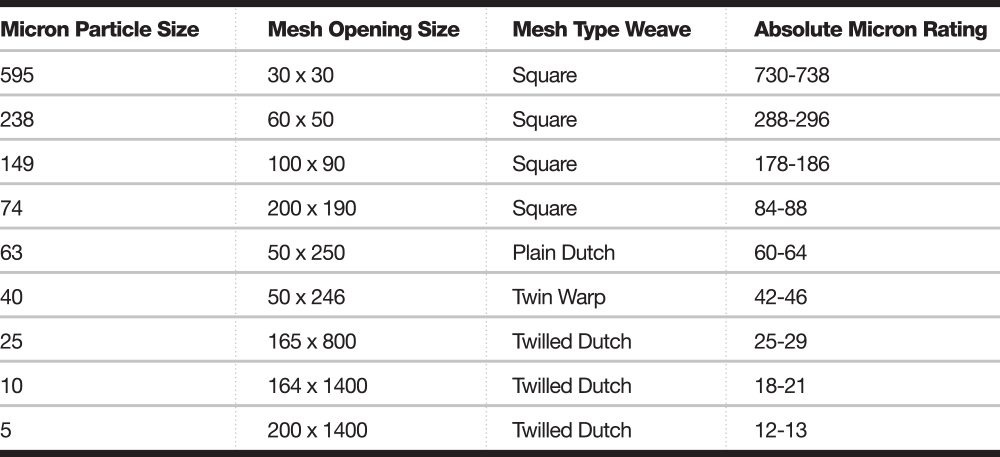
Wire cloth has rarely been associated with an absolute rating. Information is available in some of the more standard sizes, however. Remember, wire cloth people talk in terms of mesh while filter people mostly talk in terms of micron. You can use the chart below as a “general” reference to wire cloth and its specifications.

Hydraulic System Design

When a circuit design for a hydraulic system is in the planning stage, it involves much more than just determining the real intention of the system. It takes serious planning, not merely choosing components,
to ensure proper system performance. Without proper planning, total failure may occur.

See our complete white paper on Hydraulic Filtration & System Design

Three Forms of Water That Can Exist in Hydraulic Fluid

In any petroleum-based fluid, water can degrade the fluid and harm the system components.
To understand the various forms of water in hydraulic fluids, let’s define them:

1. Free water. The water that can be easily separated from oil. This water will settle to the bottom and can be easily drained off.

2. Emulsified water. Emulsification results from the turbulent action of the fluid which forms droplets so small they will not separate by settling or by centrifugal force.

3. Water in solution. Water may form in a solution with the oil. This water is invisible when in the solution, but appears as a cloud when oil temperature is lowered to the critical temperature.

Next time, we will briefly take a look at reasons “why” water can form in oil.

Fluid Conductors

In hydraulic systems there are generally three options for moving fluid from one component to another; iron pipe, steel tubing, and flexible hose. Each has its own characteristics, advantages, and disadvantages. In this newsletter, and the next two issues, we will describe some of those characteristics. 

In this newsletter we will cover iron pipe. Hopefully, it will help when making decisions about which is best to use for your application.

  • Measured on the inside diameter.
  • This is a nominal measurement.
  • Common sizes are 1/16″, 1/8″, ¼”, 3/8″, ½”, ¾”, 1″, 1 ¼”, 1 ½”, 2″, 2 ½”, 3″, 4″, 5″, 6″. All are npt.
  • Rule of thumb…to determine the size of your iron pipe, measure the outside diameter and subtract ¼”.
  • Wall thickness is specified by the schedule number. Schedule 40 is standard. Schedule 80 and 160 are available for higher pressure applications.
  • Connections are made with tapered pipe threads or welded.
  • A sealant such as Teflon tape or pipe dope must be used on threads to lubricate during assembly and seal between clearances to prevent leaks.
  • Corners are made using angled fittings such as 90° or 45°. Remember that every curve or angle in a system causes pressure drop.
  • Due to threaded connectors, iron pipe has the most potential leak points of all fluid conductors.
  • Black pipe should be used instead of galvanized pipe. The galvanizing might flake off and plug tiny pressure sensing orifices in the system. It might also react with some oil additives.

Suction Screens

OFCO’s suction screens can be used in many different applications. They are low cost, yet extremely effective. They have applications in hydraulics, water, chemical, paint, coolant, and other applications. They will not rust and are manufactured in our USA plant with male and female threads sized 3/8” to 3” npt. Mesh sizes are available from as course as 4 mesh to as fine as 200 mesh. Click on the below link to learn more about OFCO’s suction screens. 

Learn more about Pipe Mounted Suction Screens